Products in shop:

Bill of material
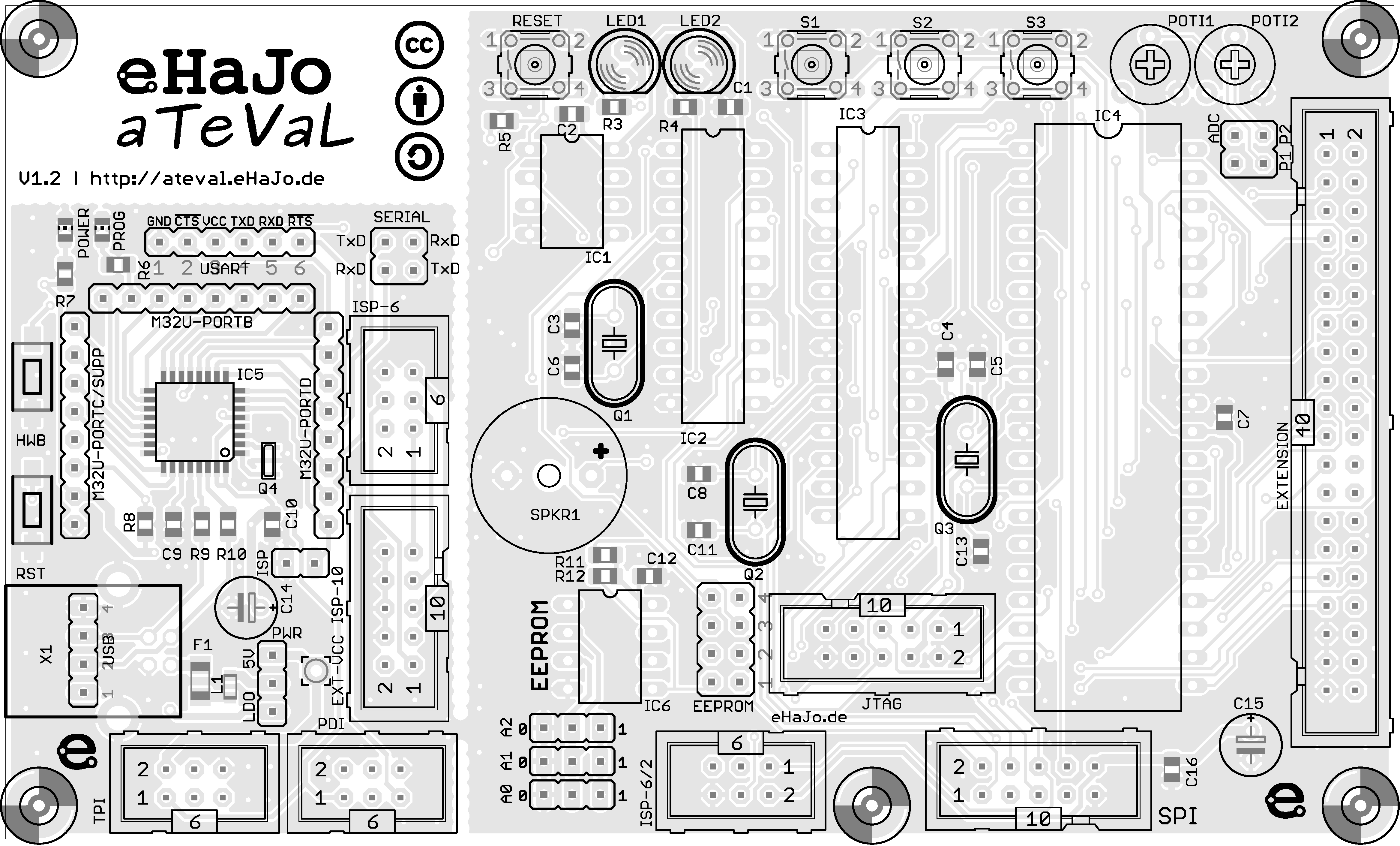
Solder the pcb in the order of the BOM
| Count | Name | Value |
|---|---|---|
| 2 | IC1, IC6 | Socket 8-polig |
| 1 | IC2 | Socket 20-polig |
| 1 | IC3 | Socket 28-polig |
| 1 | IC5 | Socket 40-polig |
| 3 | Q1-Q3 | Socket-Pins for crystals |
| 4 | RESET, S1-S3 | Push-button |
| 2 | R1, R2 | Poti 50k |
| 1 | SPKR1 | Speaker |
| 2 | C14, C15 | Elko |
| 1 | ISP-6 | Box-header 6-pin |
| 2 | ISP-10, JTAG | Box-header 10-pin |
| 1 | EXTENSION | Box-header 40-pin |
| 3 | LED1 | LED red |
| 1 | LED2 | LED green |
| 2 | ISP, PWR | header (cut off pins from 20×1-pin header) |
| 2 | SERIAL, ADC | header (cut off pins from 20×1-pin header) |
| 1 | EEPROM | header (cut off pins from 20×1-pin header) |
| 1 | X1 | USB-Connector |
All SMD-parts are already mounted on the pcb!
Circuit-diagram
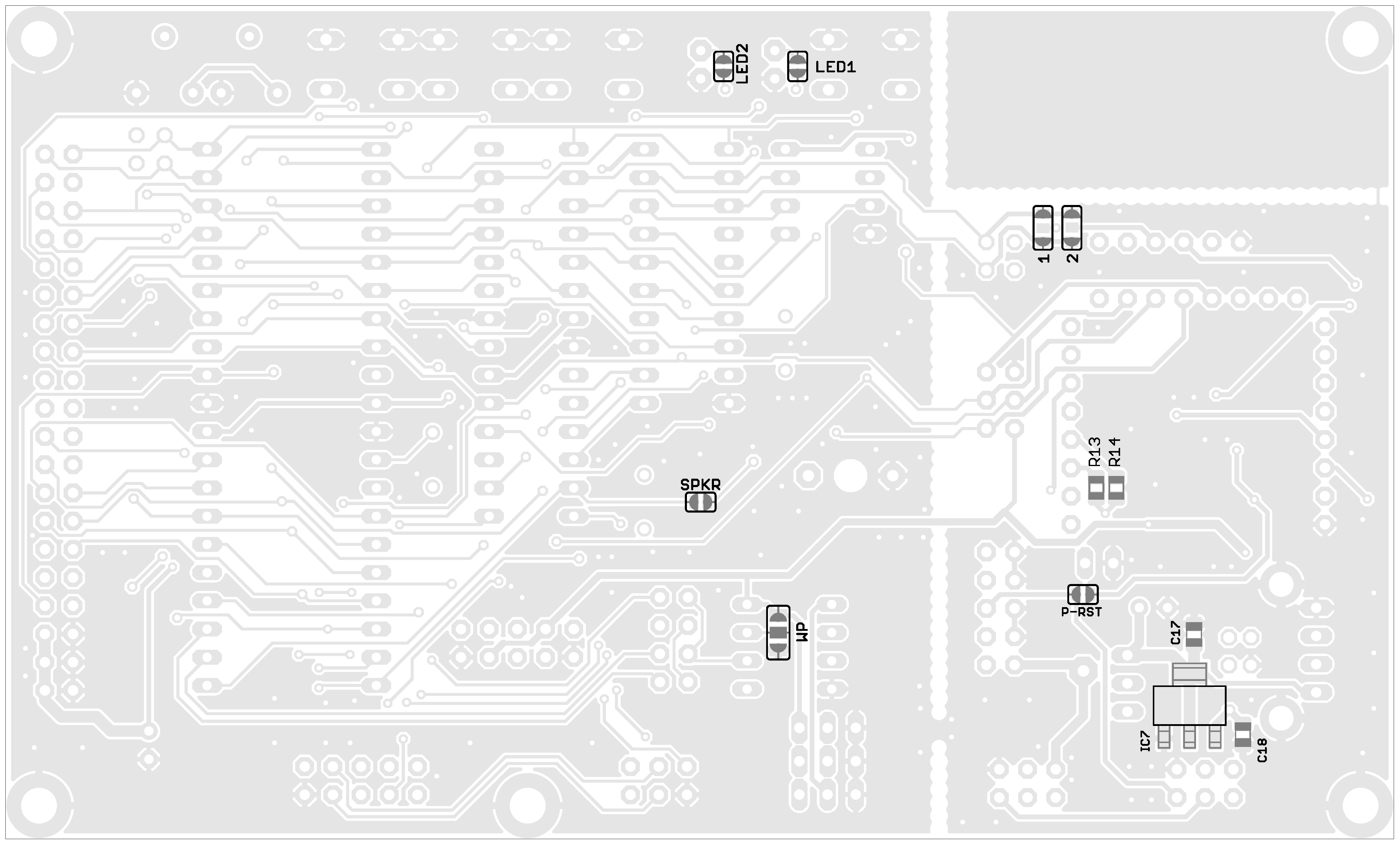
Assembly
Integrated testhardware
There's already some hardware on the aTeVaL-board for your first tests. It is connected on following pins:
| name | Attiny13 | Attiny2313 | Atmega8 | Atmega16 |
|---|---|---|---|---|
| LED 1 | X | PD6 | PD6 | PD6 |
| LED 2 | X | PD5 | PD5 | PD5 |
| Button 1 | X | PD2 | PD2 | PD2 |
| Button 2 | X | PD3 | PD3 | PD3 |
| Button 3 | X | PD4 | PD4 | PD4 |
| Poti 1 | X | X | PC1 (ADC1) | PA1 (ADC1) |
| Poti 2 | X | X | PC0 (ADC0) | PA0 (ADC0) |
| Speaker | X | X | PD7 | PD7 |
Further Information
You can find further information about the aTeVaL-board and demo code in following article: hier im Artikel über das aTeVaL-Board.
