Inhaltsverzeichnis
Assembly-instructions for the aTeVaL-Board
To get a bigger image, just klick on it.
The assembly takes about 30 minutes for a practiced hand.
Needed material
Beside the kit from our shop you need
- a soldering iron
- tin solder
- pliers (for cutting of the wires)

Solderjumper
Depending on your needs you have to set different solder-jumpers.
Version 1.2
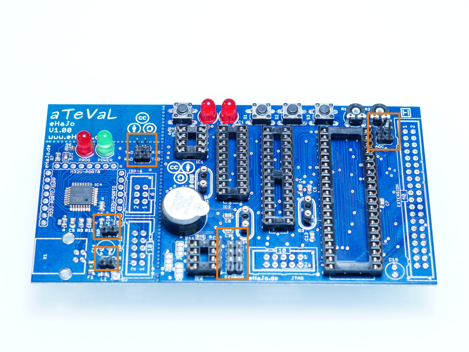
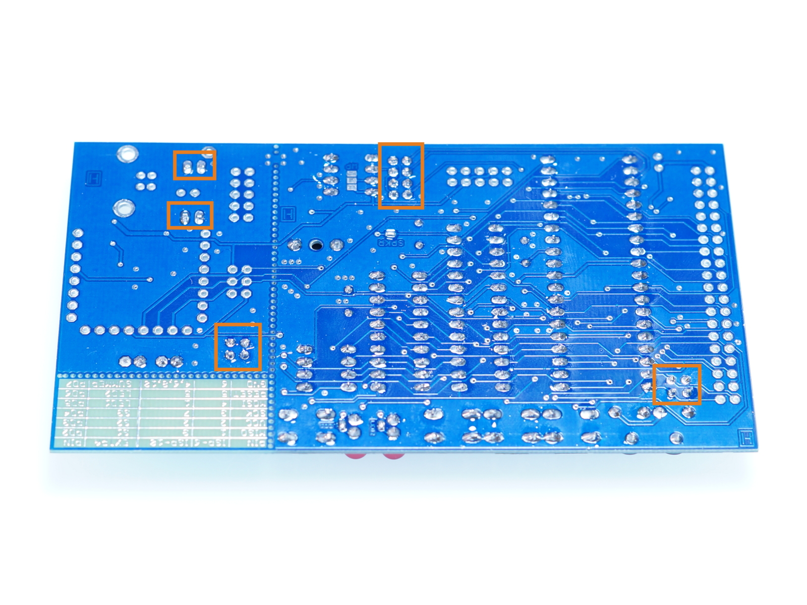
Solderjumpers for PCB-version 1.2 can be found here
Version <1.2
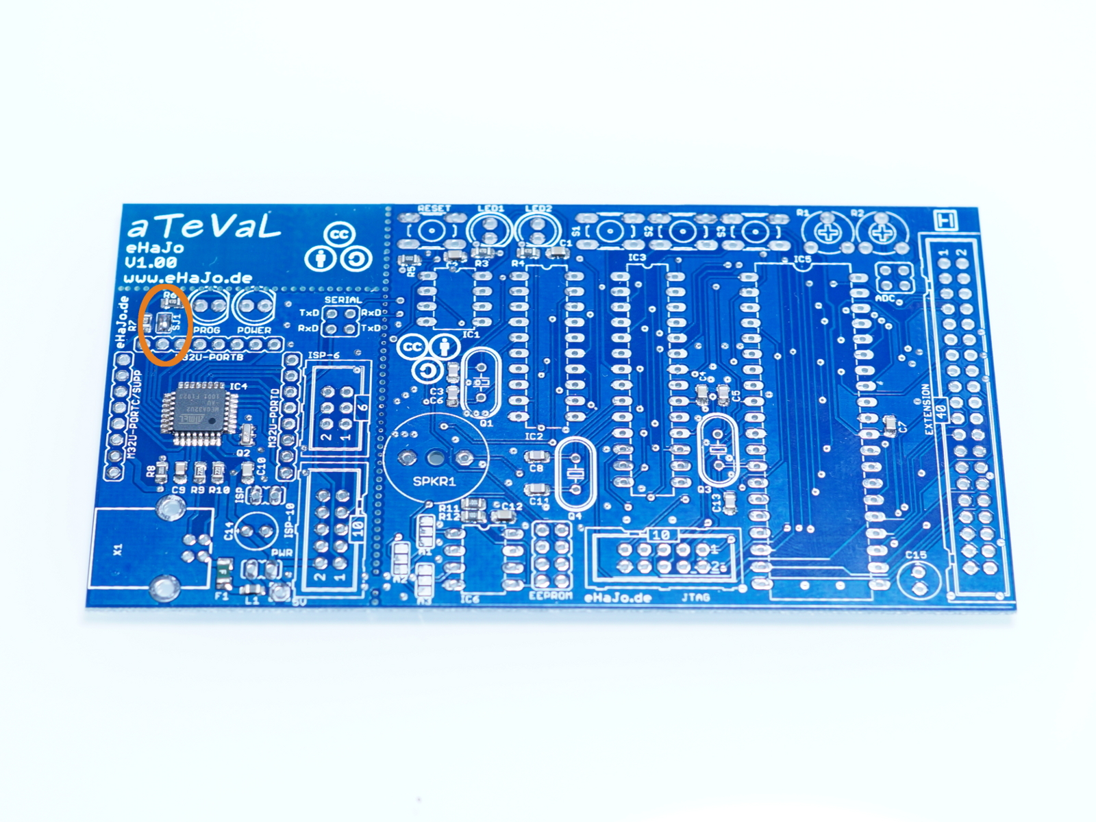
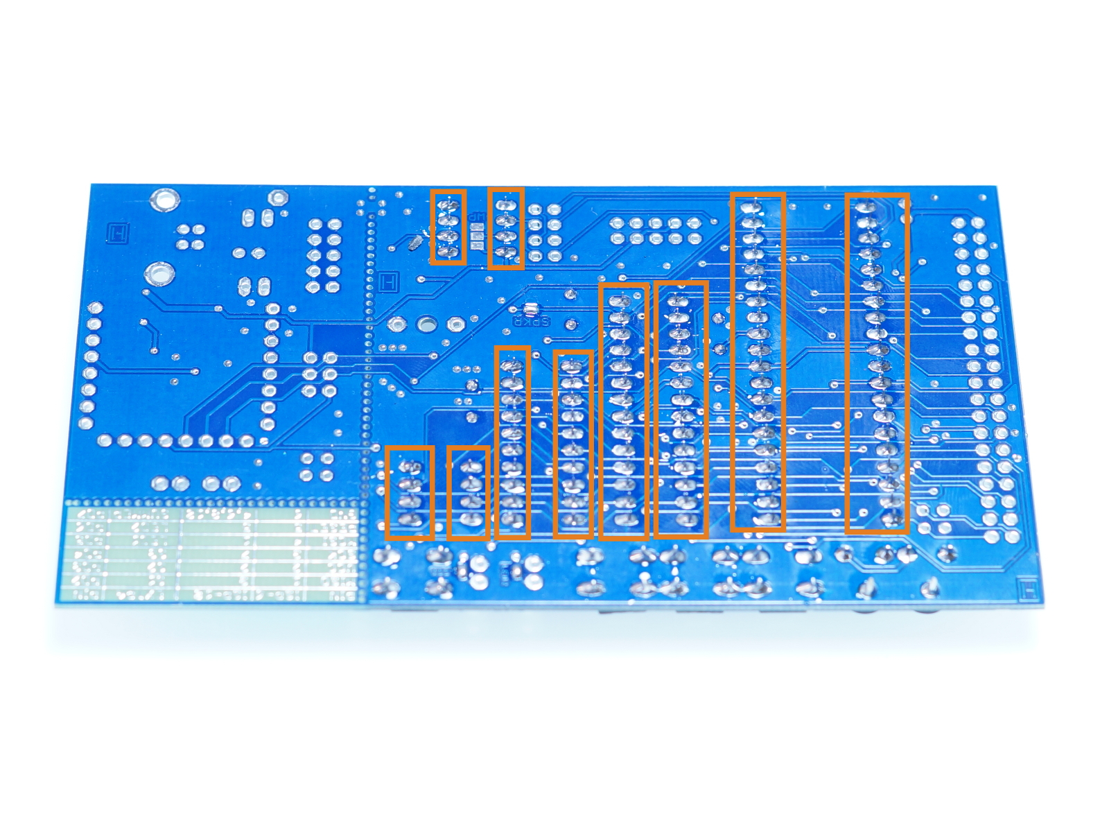
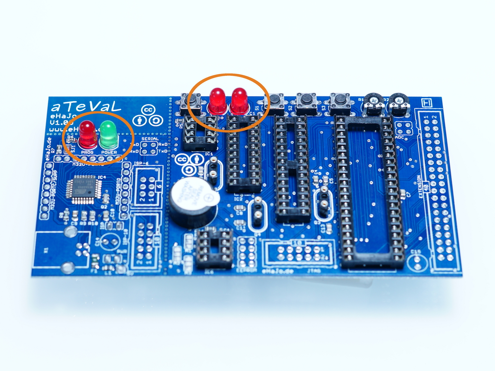
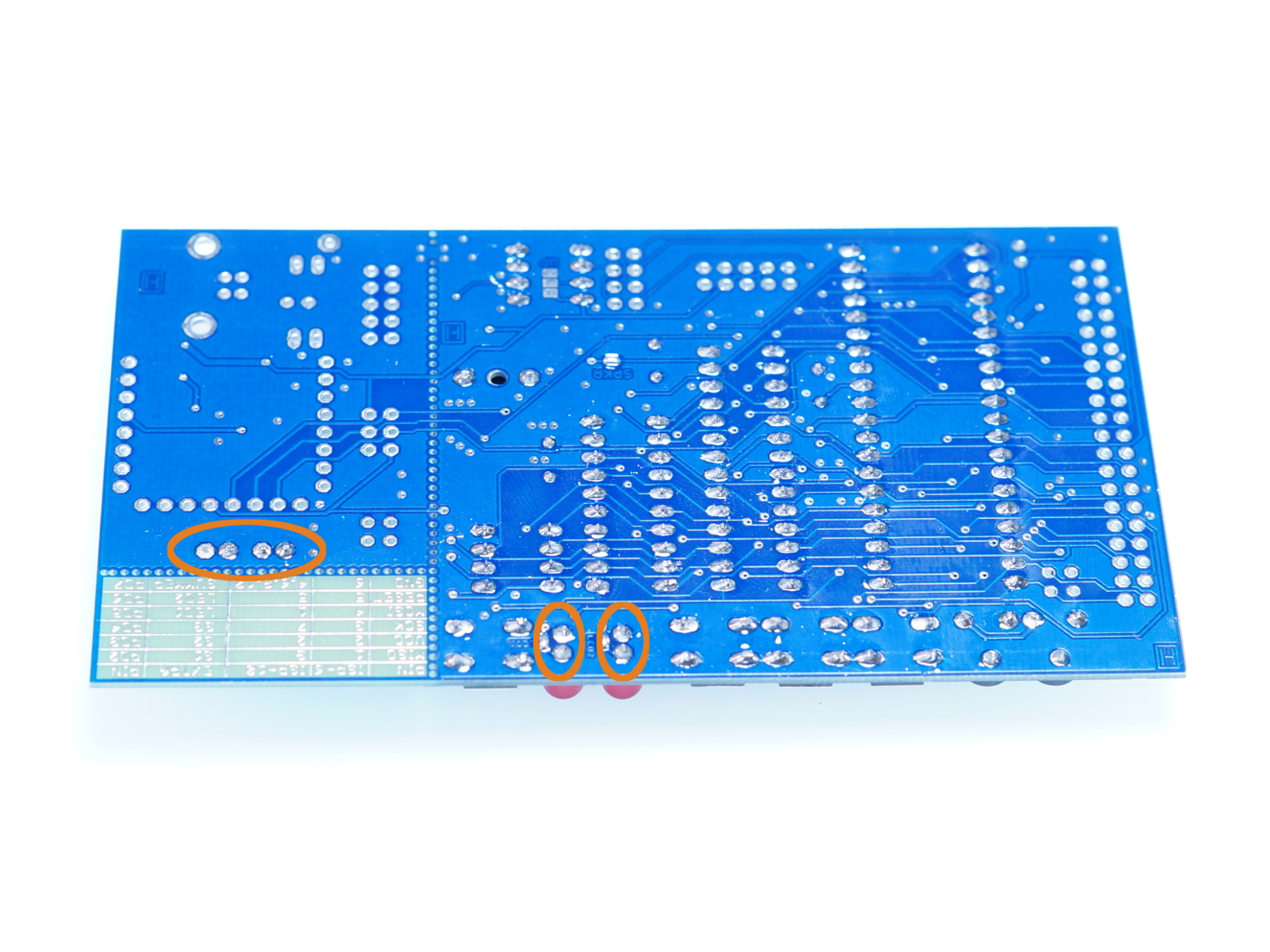
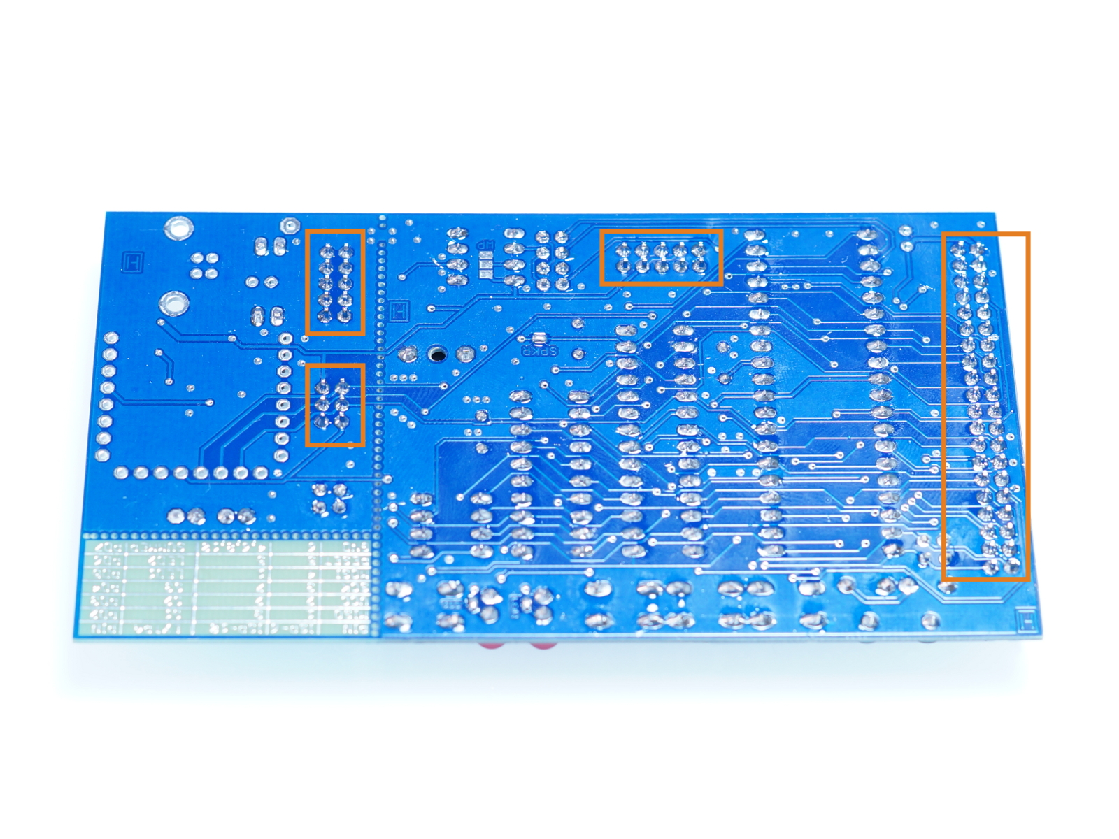
For getting feedback at the programming-progress you have to solder the solderjumper at the red LED on the programmer part:
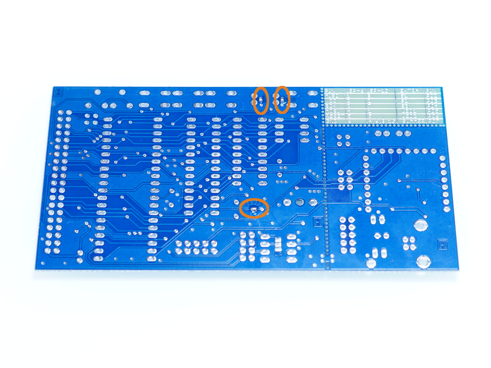
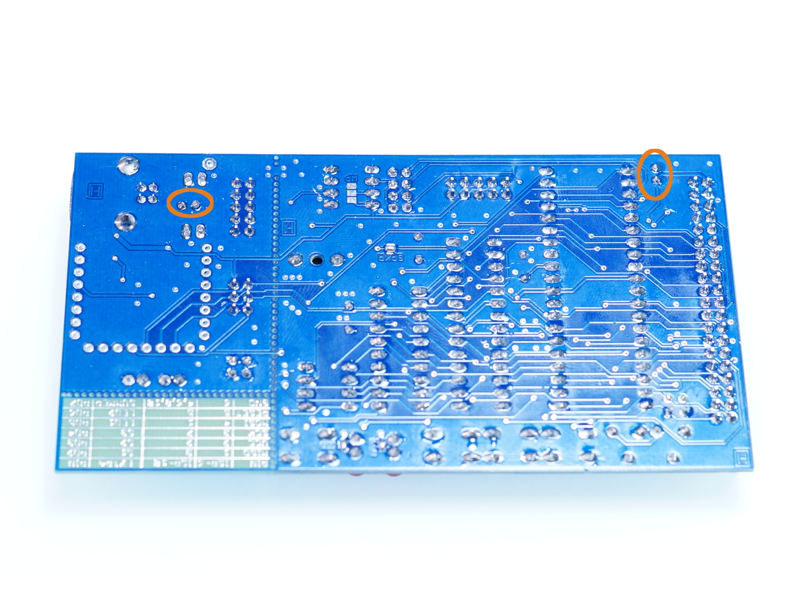
To use the LEDs and the buzzer, you have to solder the solderjumpers on the bottom side of the pcb:
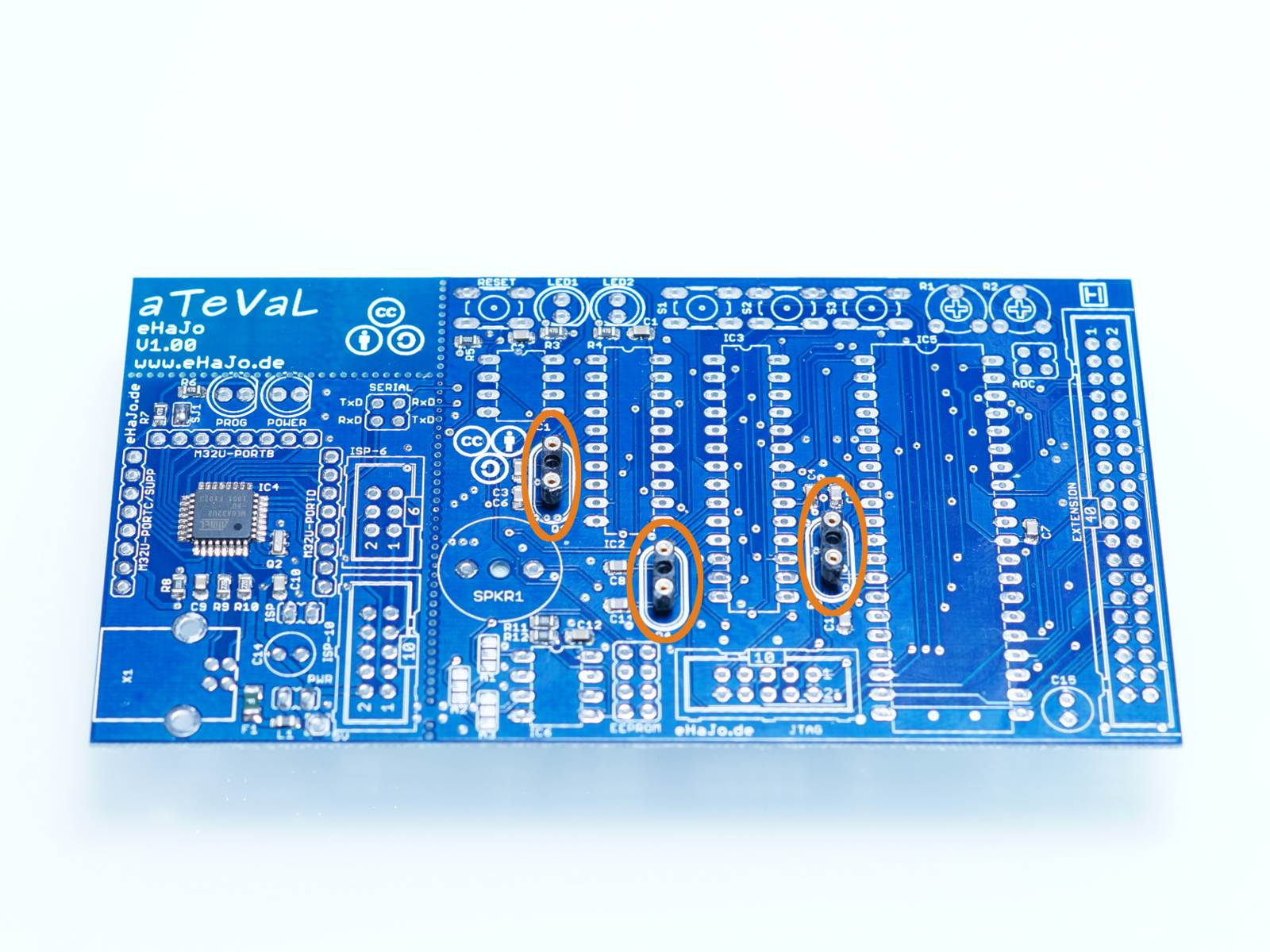
Crystal-socekts
Solder the crystal sockets:

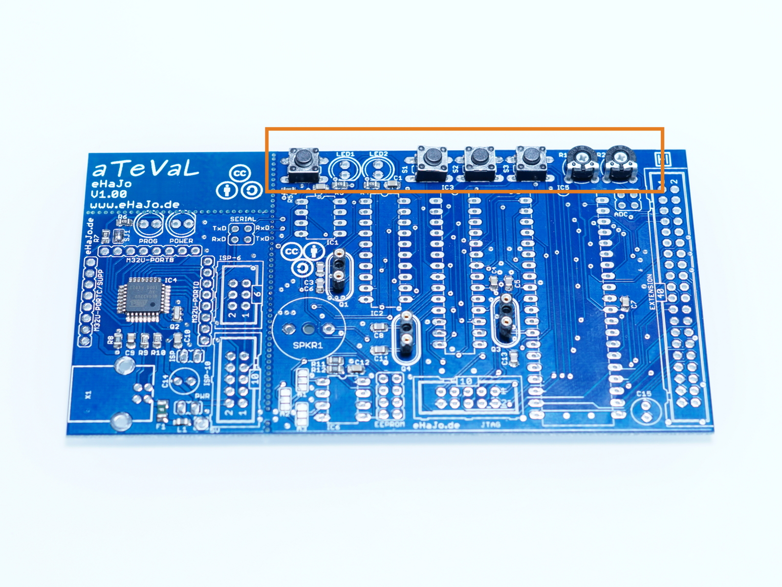
Testhardware
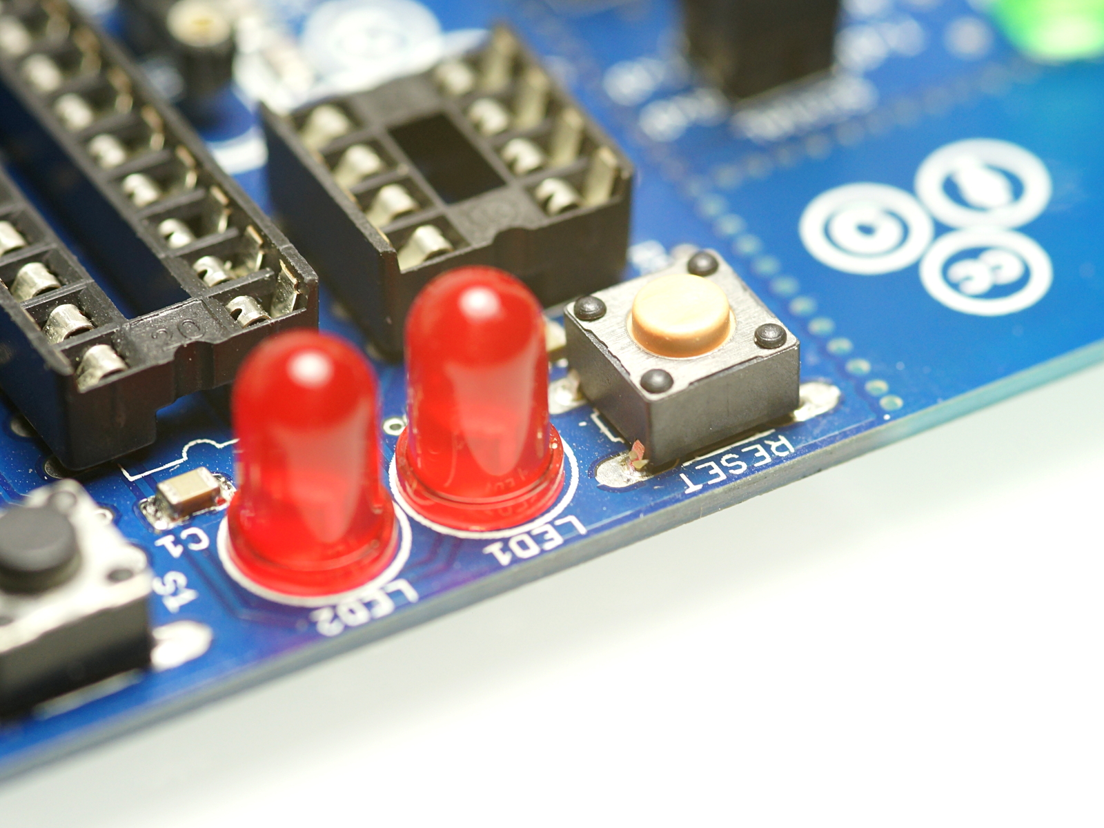
Solder the switches and the two potentiometers. (since hardware-version 1.1: the reset-button is salmon)

IC-sockets
Solder the ic-socekts.

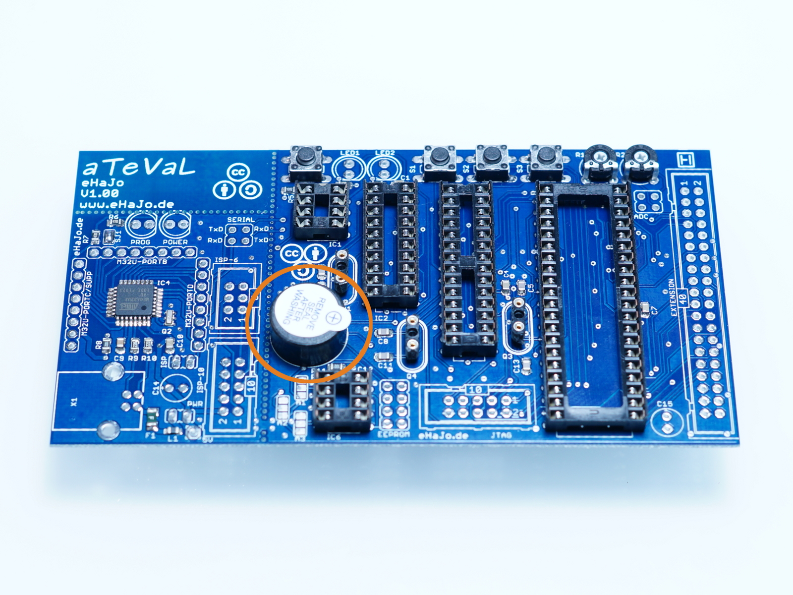
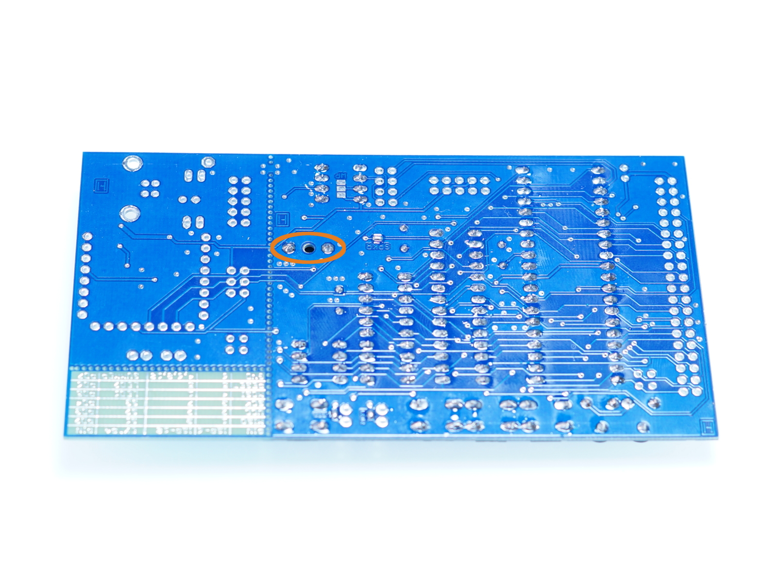
Buzzer
Solder the buzzer.
LEDs
Solder the LEDs, take care about the polarity.
Header
PCB-version 1.1:
Cut off the header for the jumper:
1-row header: 2x 2-Pins, 3x 3-Pins
2-row header: 2x 2-Pins, 1x 4-Pins
PCB-version 1.2:
Cut off the header for the jumper:
1-row header: 1x 2-Pins, 4x 3-Pins
2-row header: 2x 2-Pins, 1x 4-Pins
Solder them after cutting them.
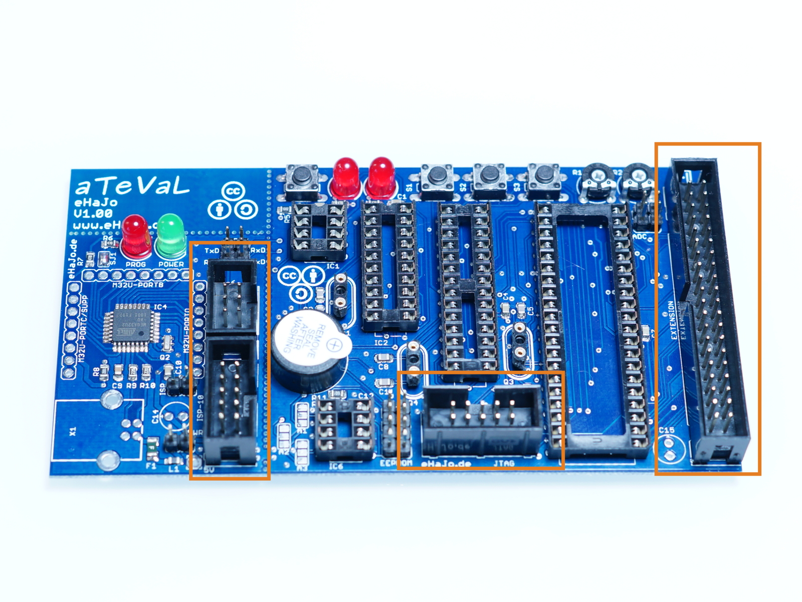
Header-socket
Solder the header-sockets, take care about the orientation.
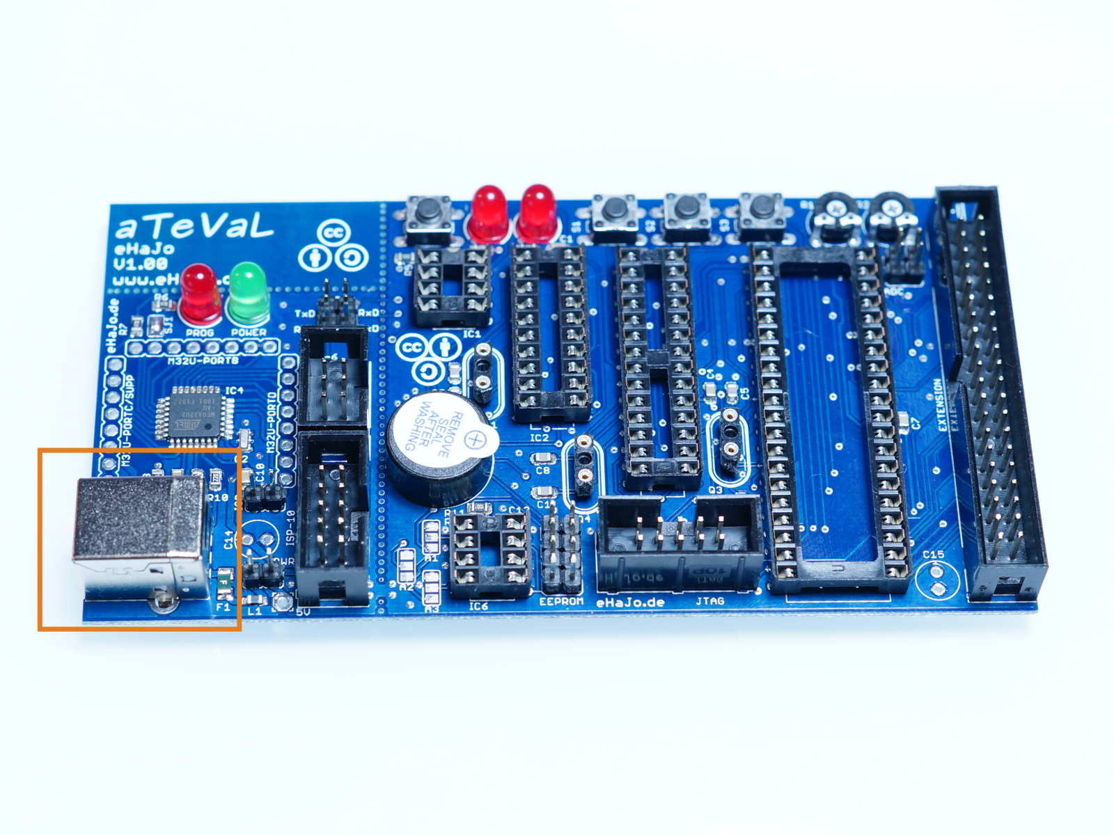
USB-B-connector
Solder the USB-B-connector.
Capacitors
Solder the capacitors, again, take care about the polarity.

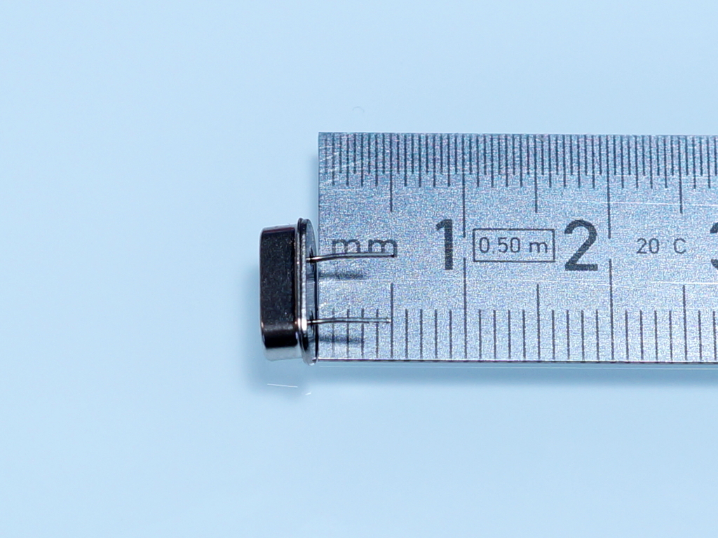
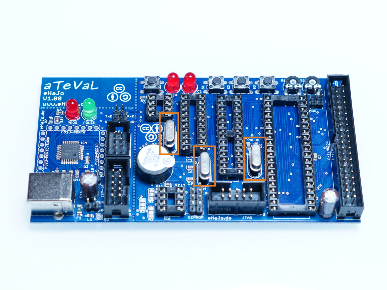
Crystals
Cut the pins that there are about 5mm left:
Put the crystal in the socket (optional):
Jumper
Plug the jumper on the header:

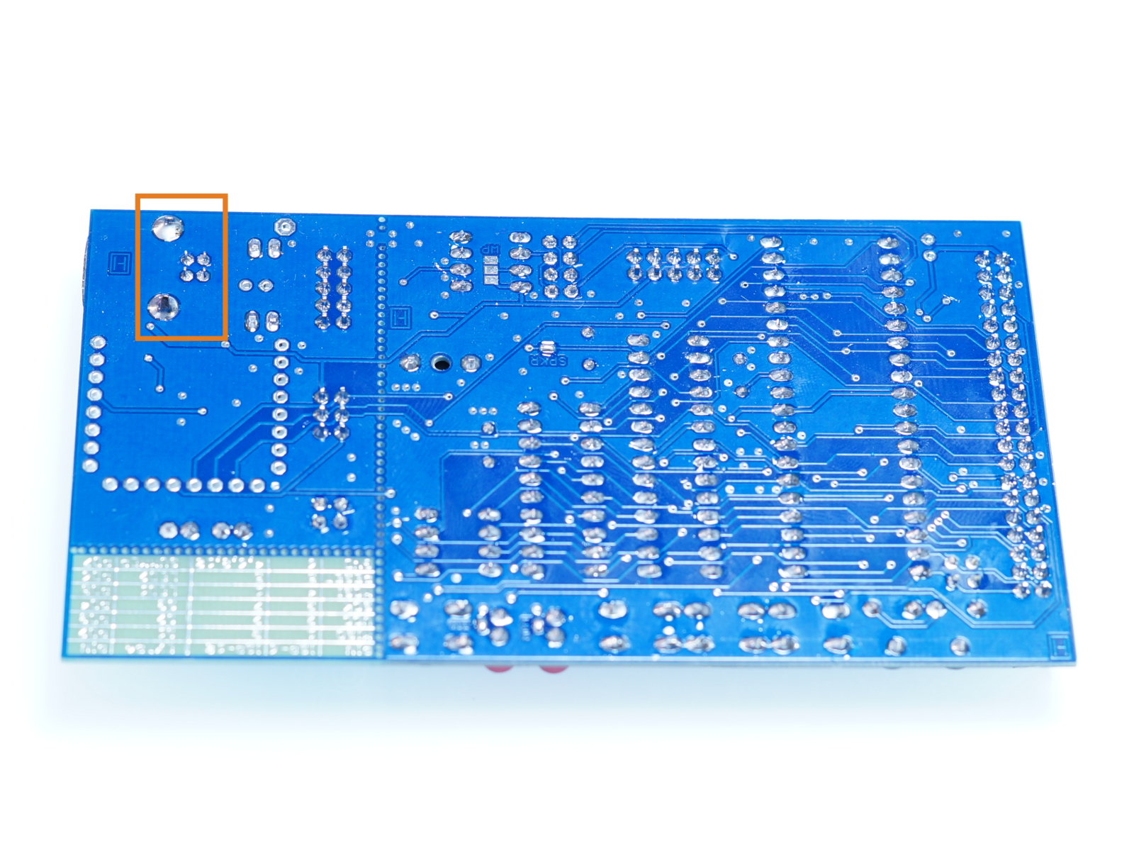
PCB-version 1.2: V1.2 has a 3-pin Powerjumper.
For power over USB: plug jumper at "5V"
For power over the optional LDO (bottom side): plug at "LDO"